

Mobile phone: 18815239758 (same as WeChat)
Phone: 0576-89881178
Phone: 0576-89825885


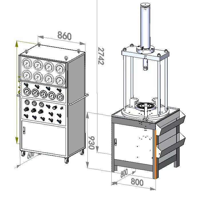
The manual control safety valve comprehensive calibration platform uses high-pressure air and high-pressure liquid (water or oil) as media to test the sealing performance, popping pressure, reseating pressure, etc. of various safety valves. Assess its pressure safety performance
Typical Applications
Used for performance testing of DN20-400mm flange safety valves, threaded safety valves, full/micro opening safety valves, conventional thick and thin flange safety valves, domestic/imported safety valves, spring direct load safety valves, safety valves with power assisted functions, and safety valves with supplementary loads.
Model Description
ZTQ-7.5-DN400
Explanation: ZTQ - Manual Control
7.5- Working pressure 48MPa
DN400- maximum diameter 400mm
Technical parameters
Host technical parameters
Pressure range: 0-7.5mpa
Test medium: air, water or oil
Boosting pump equipped with: ZTT25NL (air), ZTGD16WL (water or oil)
Control mode: manual control
Test pressure output: 1 channel;
Test valve diameter: DN 20-400mm
Computer system acquisition accuracy:+0.4%;
Pressure measurement accuracy: 0.4 level pressure gauge (optional higher pressure level);
Measurement range of pressure gauge (precision pressure gauge dual gauge calibration): 0-0.6Mpa 0-2.5MPa, 0-6MPa, 0-10MPa
Equipped with spare connectors for dual pressure gauges
Clamping method: hydraulic cylinder clamping;
Clamping force output range: 0-30 tons;
Sealing method: sealing ring/thread sealing;
Gas storage tank 4L, working pressure 15mpa
Control system power supply: 220V single-phase, 1kw
Air source equipment: The customer needs to be equipped with a 0.8MPa air compressor and a clean water source
The noise level of the calibration equipment is less than 70dB, and the noise level of the gas source machine is greater than 70dB
Technical parameters of tooling
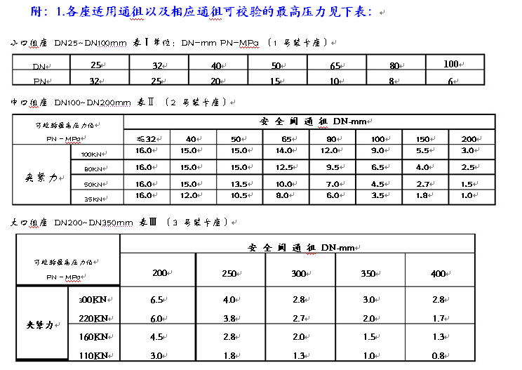
1. DN100 safety valve mounting socket
Safety valve opening: DN15 to DN100
Maximum tuning pressure: PN 32MPA
Maximum loading force: 50KN
Working medium: clean air, nitrogen
Working temperature: 0-50 ℃
Driving gas source: 0.3~0.8MPa
2. DN200 safety valve mounting socket
Safety valve opening: DN100 to DN200
Maximum tuning pressure: PN 16MPA
Maximum loading force: 100KN
Working medium: clean air, nitrogen
Working temperature: 0-50 ℃
Driving gas source: 0.3~0.8MPa
3. DN400 safety valve mounting socket
Safety valve opening: DN200 to DN400
Maximum tuning pressure: PN 8MPa
Maximum loading force: 300KN
Working medium: clean air, nitrogen
Working temperature: 0-50 ℃
Driving gas source: 0.3~0.8MPa
 Installation, debugging, and training
The system components involve high pressure (2145 PSI), and any incorrect installation or negligence can pose a threat to personal safety. On site installation must be carried out by the supplier's technical service personnel, and the user can provide relevant auxiliary assistance when needed.
Civil construction (users must complete civil construction before on-site installation)
Based on the actual situation of the user's testing site, technical personnel from both parties can jointly negotiate and propose a reasonable layout plan. The specific civil engineering design and construction will be implemented by the user.
system installation
Mechanical part:
All component equipment must be installed indoors and kept away from strong corrosive gases or liquids.
Air compressor: arranged on one side of the workspace, with a heat dissipation cover and heat exchange fan installed on the top of the air compressor. Considering the noise issue of the air compressor, it can be separated into a separate room, and the air compressor, buffer tank, and filter discharge pipelines can be collected and connected outdoors.
Boosting system: The boosting system equipment is arranged in a reasonable position in the workspace for easy maintenance and convenient movement.
Pipeline: Using hard pipeline connections has the advantages of safety and reliability, but the disadvantage is inconvenient layout and installation. The hose connection has the advantages of simplicity and convenience, but its safety should be taken into account during use. According to the on-site situation, soft and hard pipelines can also be mixed to fully utilize their respective advantages
Electrical part:
The installation site of the pressure testing system must provide a separate 220V AC power supply (to be provided by the user) from the factory's main distribution room.
All components of the equipment must be reliably grounded.
The signal lines are all shielded cables and are buried in separate slots from the power cables to prevent spatial interference.
Before the installation is officially put into testing, it is necessary to check each item and ensure that the signal and control actions are correct before starting the test
